

 English
 Español
 日本語
A wheel can turn smoothly in your hand and still not go into its bracket. The diameter was right and the groove looked right, yet the parts would not come together. Mounting problems like this rarely come from the wheel alone.
A Roller Mounting Assembly works as a chain of connections. The wheel sits on a shaft, the shaft is held by a bracket, and the bracket is fixed to the equipment frame. If one connection is poorly matched, the whole assembly is affected.
Follow the Chain From Wheel to Frame
The sequence below shows how a wheel is held in place by Metal Hardware Components:
Wheel → Shaft → Bearing (where used) → Bracket → Fixing holes → Equipment frame
Each arrow marks a place where two parts must agree in size and position.
- The wheel is the part that touches the track or guiding surface. Its diameter, width, contact profile and material (metal or plastic, depending on the product) are chosen for that surface. Its central bore connects it to the other parts.
- The shaft supports the wheel and sets where the wheel sits in the unit. Shaft designs differ between products, so one form should not be treated as standard.
- The bearing, where a design uses one, supports the turning motion. It has to suit the wheel body, the shaft and the space inside the unit. Bearing type and performance depend on each product's own data.
- The bracket holds the wheel and shaft in position and connects the unit to the equipment. A Roller Wheel Bracket may include mounting holes, bends or slots, and its shape can be adapted to the available space.
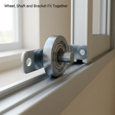
HUNE's Machined Steel Sliding Window Single-Wheel Roller Assembly with Stamped Bracket shows this chain in one product. It has a machined steel wheel with a central bearing and shaft, mounted in a stamped iron bracket. The bracket has electroplated surface treatment and mounting holes at both ends. The unit is intended for matching sliding window track systems.
Three Common Ways the Wheel Is Joined to the Metal
Connection methods vary by product. The descriptions below show general design thinking, not a fixed standard.
Shaft-mounted structures. The wheel meets the shaft through its central hole, and the shaft connects to the bracket. The shaft may be secured by riveting, press fitting or another mechanical joint. Which one applies depends on the actual product, so confirm it with the supplier.
Bearing-fitted structures. The bearing sits inside the wheel body or in a space designed for it. The shaft and bearing must be compatible, and the bracket must leave enough room for both. The wheel body, bearing and bracket share one small space, so their dimensions should be read together.
Bracket-mounted units. The wheel is installed in a metal Roller Wheel Bracket or housing, which connects to the door, window or equipment frame. Its holes and outline must meet the installation requirements. Some designs add slots or other helper features. The single-wheel product described above follows this layout. Nothing beyond its published structure is implied here.
Reading the Metalwork Behind the Wheel
Here the metal parts become the main subject.
| Form | What It Does | What to Confirm |
|---|---|---|
| Stamped bracket | Sheet metal is stamped and bent into the needed shape, with holes placed to suit the wheel position | Material, bend positions, hole dimensions |
| Housing or supporting plate | Contains or supports the wheels, and side walls can limit where each wheel sits | Internal space, wall shape, fit inside the equipment |
| Adjustable mounting feature | Slots or similar details allow position changes in some designs | Whether adjustment exists and how it works |
Not every bracket offers height or position adjustment, so check this on the actual product.
Housing designs can differ widely. The 158 mm Tandem Sliding Door and Window Roller Assembly is one example. Its two wheels sit one behind the other along a slim metal housing, and the housing has mounting holes and slots.
When the Fit Goes Wrong: Symptoms and Likely Causes
Most installation trouble appears where two parts meet. The table links what you notice to what is worth checking.
| What You Notice | Area to Check |
|---|---|
| The wheel will not drop into the bracket | Wheel width and the bracket's inner space |
| The shaft will not pass through the wheel | Bore size and shaft size |
| The unit assembles but will not fix to the frame | Hole positions and spacing on the bracket |
| The wheel sits too high or too low in the track | Mounting height and wheel diameter |
| The wheel runs poorly on the track | Groove shape and track direction |
Checking each part's size on its own can mislead. A wheel, bearing and shaft may each measure correctly and still fail as a group, because the relationship between them matters more than any single value.
An assembly that goes together on a bench has passed only the first test. The second test is whether it installs correctly in the finished equipment, with the right position, orientation and space.
Preparing a Brief for Your Supplier
A supplier can only evaluate what it receives. Fill in the items below and send them together with your drawing or photos:
- Application: equipment type, track type, movement direction and working environment
- Wheel: diameter, width, bore, profile and material
- Shaft: dimensions and how it is fixed
- Bearing: arrangement, if any
- Bracket or housing: drawing or sample, material and shape
- Mounting holes: positions, sizes and spacing
- Installation space: available dimensions inside the equipment
- Reference: existing sample or photos
A technical drawing is the clearest attachment. It shows how the parts relate in position and size, and it makes hole locations plain.
If you only have an existing sample, send it. It shows the outline, the connection structure and how the old unit was installed. Treat it as a reference, because key dimensions should be reconfirmed before production. With these details, a review of your Roller Mounting Assembly has a solid starting point.
From First Drawing to Approved Sample
Custom development is less about changing a wheel's size and more about making the wheel and the metalwork agree. The path usually runs as follows:
Application review → Structure assessment → Drawing confirmation → Sample evaluation → Design adjustment → Production preparation
The supplier first learns where the roller will be installed and how it moves, then reviews how the wheel, shaft, bearing and bracket are arranged. Dimensions and mounting relationships are checked against the drawing. A sample lets both sides inspect the assembled part and its installation fit. Changes found during evaluation are discussed, and manufacturing requirements are settled once the design is approved.
Scope and timing are agreed for each project.
Quick Answers
How is a roller wheel fixed to a metal bracket? Usually through a shaft, often with a bearing, held in the bracket by a mechanical connection. The exact method depends on the assembly design.
What is the difference between a roller bracket and a roller housing? A bracket mainly provides the mounting connection. A housing may also contain and support the wheel. Names and roles vary with product structure.
Can different roller wheels use the same metal bracket? Not necessarily. Wheel size, bore, mounting position, bearing arrangement and inner space all need checking. One Roller Wheel Bracket should not be assumed to fit several wheel designs.
What causes roller assembly installation problems? Typical causes are dimensional mismatch, hole position errors, an unsuitable shaft structure, limited space and a track that does not match.
Can a roller mounting assembly be customized from a drawing? A structure review can often begin from a drawing. Feasibility is confirmed against the real product requirements.
Mounting succeeds when the wheel, shaft, bearing, bracket and fixing holes work as one system, and when that system matches the equipment it goes into. A drawing or sample of the full assembly says more than a wheel dimension alone. A supplier's understanding of how wheels and Metal Hardware Components fit together is also worth examining.
HUNE offers roller assemblies with stamped brackets and supports customization. Send a drawing or sample, and the structure can be reviewed together.