Machined Steel Sliding Window Single-Wheel Roller Assembly with Stamped Bracket: Structure, Selection, and Manufacturing Guide
A sliding window that feels stiff does not always need a new wheel. A bent bracket, worn bearing, damaged track or incorrectly positioned roller can produce similar symptoms. Identifying the cause requires checking the complete rolling and mounting system.
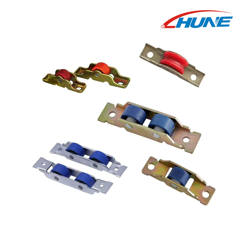
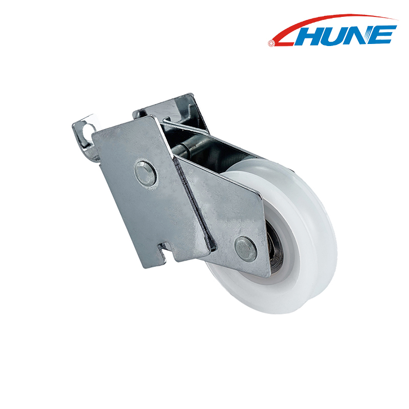
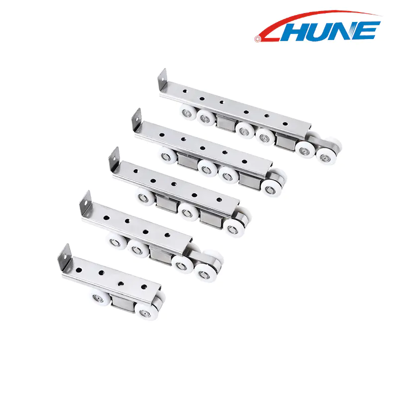
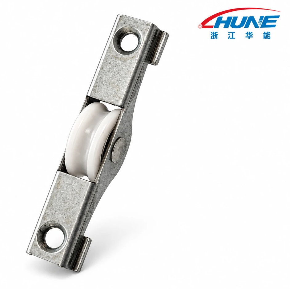
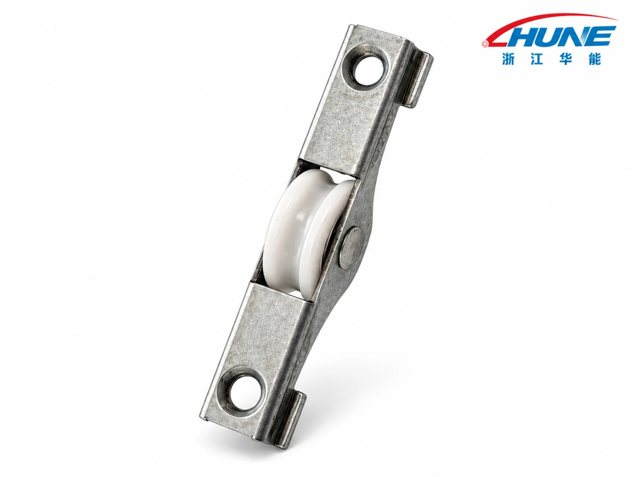
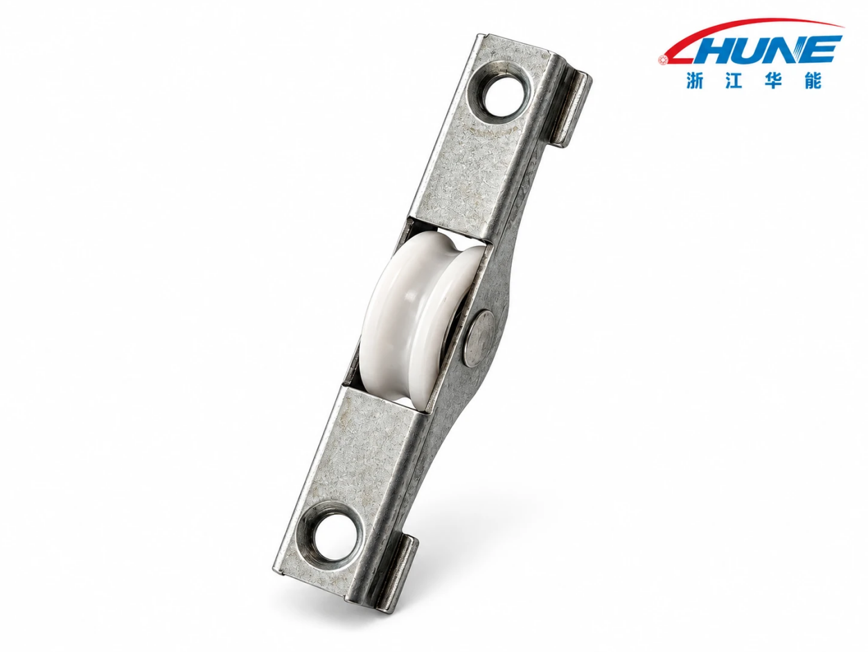
The HUNE Machined Steel Sliding Window Single-Wheel Roller Assembly with Stamped Bracket combines a single machined steel wheel, a central bearing and axle, and a stamped iron bracket with an electroplated finish. It is a component for compatible sliding window systems.
Selecting the correct assembly means matching both interfaces: the wheel must suit the track, and the bracket must suit the window’s mounting structure. This guide explains the product’s construction, selection criteria, manufacturing considerations and common installation problems.
What Is This Sliding Window Roller Assembly?
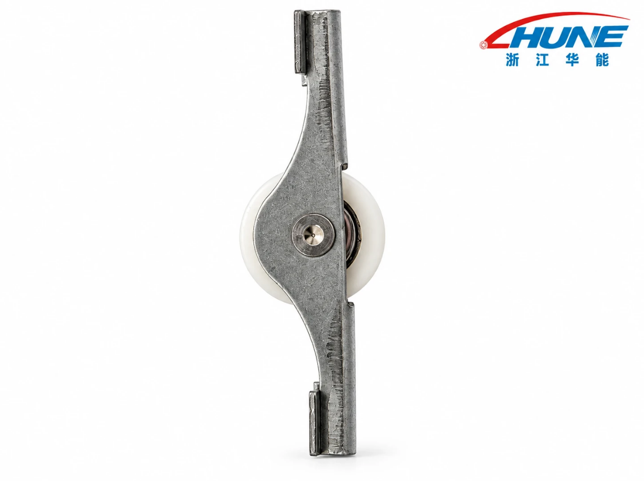
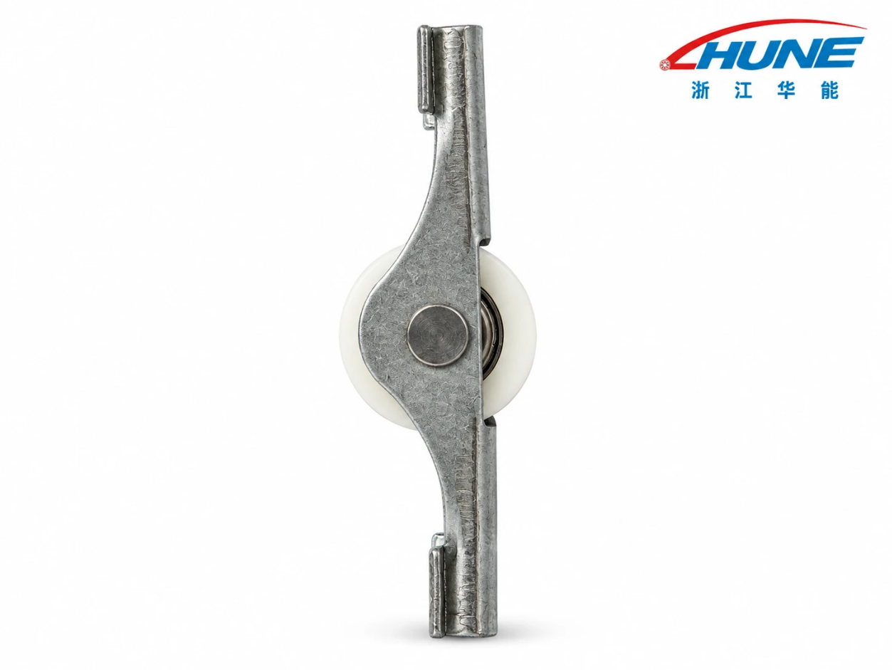
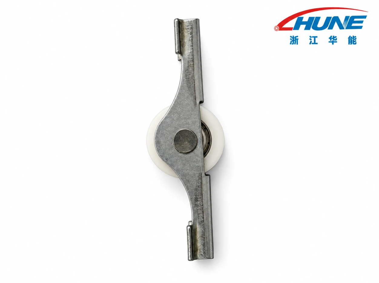
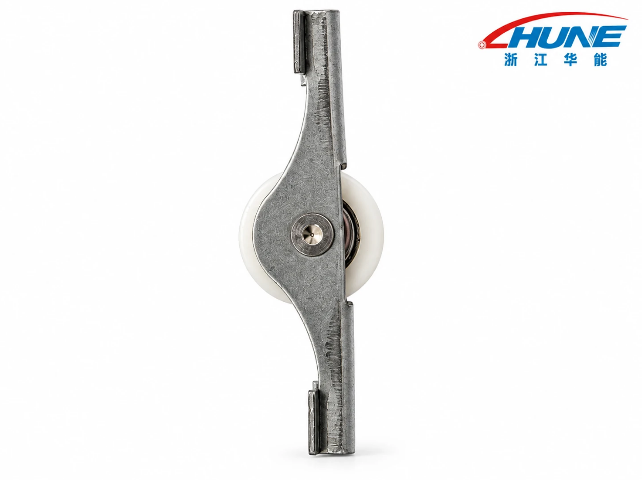
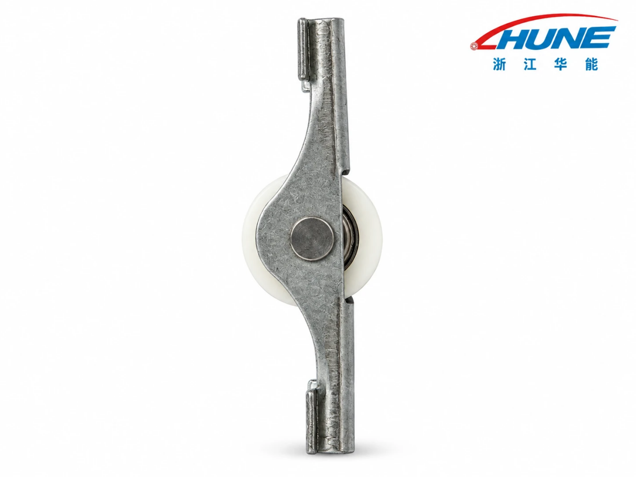
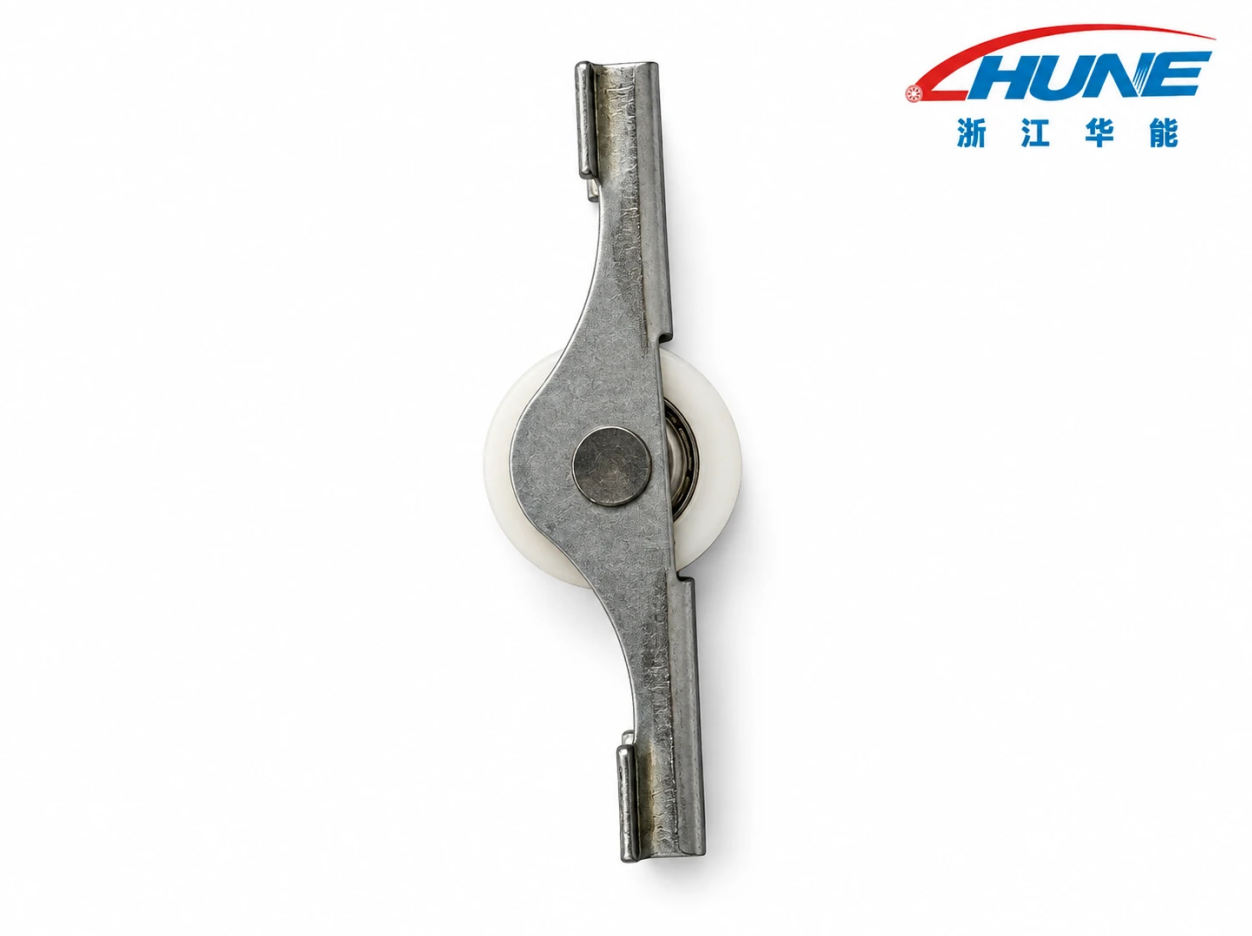
This assembly holds one machined steel wheel within an elongated stamped bracket. The bracket connects the roller to the window’s mounting structure, while the wheel rotates along a compatible track during sash movement.
The wheel is positioned in the central section of the bracket. One circular mounting hole is located near each end, providing a two-hole mounting layout.
Its defining features are:
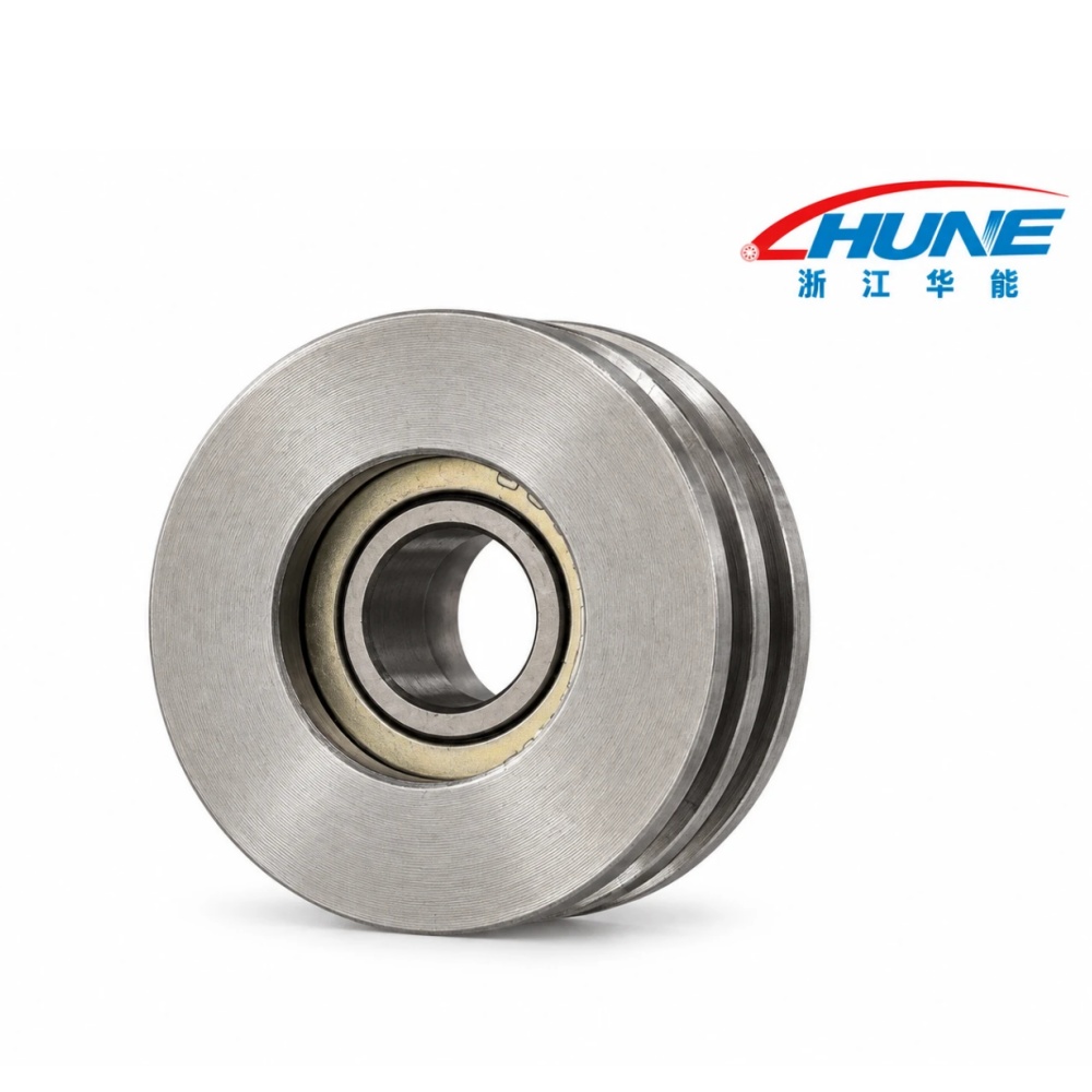
- One machined steel wheel with a circumferential groove.
- A central bearing and axle supporting wheel rotation.
- A stamped iron bracket with formed mounting features.
- An electroplated bracket finish.
- Two end mounting holes.
These features describe the component’s construction. They do not establish a universal fit, load rating or compatibility with every sliding window system.
Main Components and Their Functions
Each component contributes to rotation, positioning or mounting.
| Component |
Main Function |
Key Selection Details |
| Machined steel wheel |
Provides the running surface against the track |
Diameter, width, groove geometry and surface finish |
| Central bearing |
Allows rotation between the wheel and axle |
Bearing dimensions, fit, condition and operating requirements |
| Axle |
Supports the wheel and defines its rotational axis |
Diameter, alignment and retention |
| Stamped iron bracket |
Positions the wheel and connects the assembly to the mounting structure |
Thickness, formed geometry and mounting references |
| Electroplated bracket finish |
Provides the specified surface treatment |
Plating specification and environmental suitability |
The complete assembly must be evaluated together. A wheel that rotates freely before installation can still bind if the bracket is distorted or the track is incompatible.
How the Assembly Works
As the window sash moves, contact with the track causes the wheel to rotate. The bearing supports rotation around the axle, while the bracket maintains the wheel’s installed position.
The assembly performs three related functions:
- Rolling contact: The steel wheel runs along the compatible track.
- Rotational support: The bearing and axle support wheel movement.
- Mounting and force transfer: The bracket connects the roller to the surrounding window structure.
The forces acting on the assembly depend on its position within the window system. Other rollers, guides, frame features and retention components also influence sash support and alignment.
This roller is one component of the complete window system, not an independent alignment or anti-derailment device.
Why the Stamped Bracket Matters
The bracket determines where the wheel sits relative to the mounting surface and track. Its geometry is therefore as important as the wheel dimensions.
Important bracket characteristics include:
- Material and thickness: Affect stiffness and resistance to deformation.
- Mounting-hole positions: Determine compatibility with existing fixing points.
- Wheel-axis position: Establishes the installed running height.
- Bend geometry: Influences clearance, alignment and structural behavior.
- End tabs and folded edges: Must match the available installation space.
- Surface treatment: Must suit the specified service environment.
An incorrectly positioned or bent bracket can produce uneven track contact, higher movement resistance and localized wear.
How to Select the Correct Sliding Window Roller Assembly
Selection should begin with the window design, mounting dimensions and track geometry—not appearance alone.
Confirm the Application
This product is identified for sliding window use. Compatibility with sliding doors, furniture systems or equipment guides should not be assumed without technical review.
For the intended window system, establish:
- Sash dimensions and weight.
- Number and location of roller assemblies.
- Track material, profile and condition.
- Mounting space and fixing arrangement.
- Expected opening and closing frequency.
- Exposure to moisture, dust or cleaning chemicals.
These details help define the requirements for the wheel, bearing, bracket and mounting structure.
Check the Critical Dimensions
Replacement parts should be compared using the same measurement references.
| Dimension |
What to Check |
Why It Matters |
| Wheel outside diameter |
Maximum diameter of the steel wheel |
Affects running height and clearance |
| Wheel width |
Overall axial width |
Determines track and bracket clearance |
| Groove geometry |
Shape, width and depth |
Determines compatibility with the track |
| Bearing dimensions |
Bore, outside diameter and width |
Establish fit with the axle and wheel seat |
| Bracket thickness |
Thickness at specified locations |
Affects fit and structural behavior |
| Mounting-hole layout |
Hole diameter and center-to-center spacing |
Determines fixing compatibility |
| Wheel-axis position |
Axle center relative to mounting references |
Establishes installed wheel position |
| Overall assembly envelope |
Complete length, width and height |
Confirms available installation space |
Matching these dimensions reduces the risk of selecting a visually similar but incompatible component.
Match the Machined Steel Wheel to the Track
The wheel has a grooved running surface, but the exact groove dimensions must be confirmed from the product drawing or measured sample.
Check the relationship between:
- Wheel groove and track profile.
- Wheel width and surrounding clearance.
- Steel running surface and track material.
- Wheel alignment and direction of travel.
A steel wheel should not be treated as a direct substitute for a plastic wheel without reviewing the contact conditions. Material changes can affect noise, contact stress and wear on the mating track.
Steel construction alone does not establish higher load capacity or longer service life. Performance depends on the full design, material specification, finish and operating conditions.
Evaluate Loads Across the Complete Assembly
The allowable operating load depends on more than the wheel. The bearing, axle, bracket, fasteners and window structure must all withstand the forces applied to them.
Relevant conditions include:
- Static load: Forces while the sash is stationary.
- Dynamic load: Forces during movement.
- Impact load: Forces caused by abrupt operation or track irregularities.
- Side load: Forces acting across the wheel or bracket.
- Repeated cycles: Movement that contributes to wear and fatigue.
Multiple rollers do not necessarily share the sash weight equally. Track level, installation tolerances and bracket stiffness can shift more load onto one support point.
Use a verified assembly rating where available. Do not derive capacity from wheel diameter, steel material or wheel count alone.
Check Bearing Fit and Rotation
The bearing must fit correctly within the machined wheel and around the axle.
Review:
- Bearing-to-wheel seat fit.
- Bearing bore and axle fit.
- Axial clearance and retention.
- Alignment of the axle and bracket.
- Bearing condition and contamination protection.
Excessive interference can affect bearing clearance and increase rotational resistance. An overly loose fit can allow unwanted movement. The correct fit should follow the bearing specification and assembly drawing.
Single-Wheel and Double-Wheel Alternatives
Wheel count changes the contact arrangement, but it does not independently determine performance.
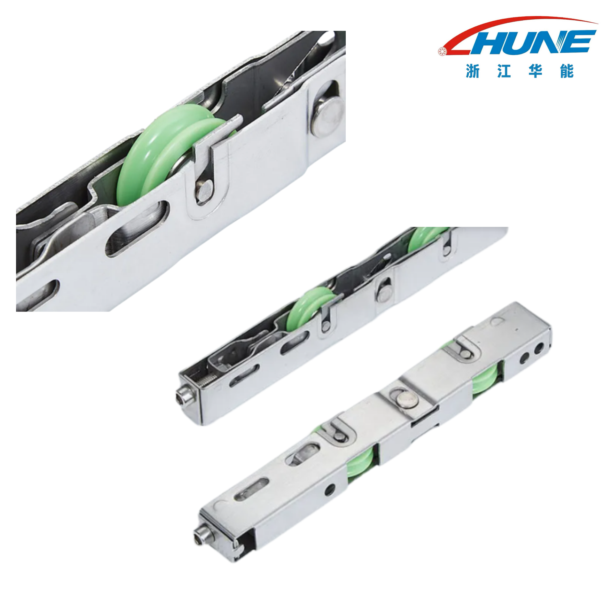
| Design |
General Arrangement |
Main Selection Consideration |
| Single-wheel assembly |
One wheel within the mounting assembly |
Space, track fit, alignment and required load |
| Double-wheel assembly |
Two wheels within a support arrangement |
Wheel spacing, load sharing and overall geometry |
| Adjustable assembly |
Includes a designed wheel-position adjustment |
Adjustment range, access and locking method |
These designs are not automatically interchangeable. A replacement must match the window’s mounting and running geometry.
Manufacturing and Inspection Considerations
Machining the Steel Wheel
The steel wheel requires controlled geometry at the running surface and bearing seat. Manufacturing specifications should address:
- Wheel outside diameter and width.
- Groove shape and dimensions.
- Bearing-seat diameter and depth.
- Concentricity between the bearing seat and running surface.
- Face runout.
- Surface finish and edge condition.
Concentricity and runout influence how consistently the wheel contacts the track. Bearing-seat accuracy affects fit and assembly retention.
The steel grade, tolerances and any wheel surface treatment should be stated separately in the specification. They cannot be established from the product name alone.
Stamping and Forming the Iron Bracket
The bracket is produced by stamping and forming iron into the required mounting shape.
Inspection should verify:
- Material thickness.
- Mounting-hole diameter and spacing.
- Central wheel opening.
- Bend positions and angles.
- End-tab geometry.
- Flatness at mounting surfaces.
- Burrs and sharp edges.
A bracket can meet its overall length requirement and still position the wheel incorrectly if its bends or axle location are out of tolerance.
Electroplating the Bracket
The bracket has an electroplated finish. The specific plating type, thickness and corrosion-resistance requirements should be defined in the purchasing specification.
Relevant checks include coverage, adhesion and the condition of functional surfaces. Plating effects on closely controlled holes or fits should also be considered.
“Electroplated” describes a surface-treatment process; it does not, by itself, establish a corrosion-performance rating.
Final Assembly Inspection
Once the wheel, bearing, axle and bracket are assembled, inspection should cover:
- Free rotation without bracket interference.
- Secure bearing and axle retention.
- Correct wheel position.
- Appropriate axial clearance.
- Overall dimensional conformity.
- Visible damage or bracket distortion.
Where required, operating-cycle and load tests should represent the intended window application. A free-rotation check alone does not establish long-term performance.
Procurement Information
A complete inquiry should include the drawing or reference sample, required quantity and applicable acceptance criteria.
Specify the wheel dimensions, groove profile, bearing requirements, bracket thickness, hole layout, electroplating requirements and mounting geometry.
This gives the supplier a clearer basis for assessing feasibility and helps maintain consistency between sample approval and repeat orders.
Installation, Troubleshooting and Frequently Asked Questions
Installation quality and track condition can affect performance even when the roller itself meets specification.
Installation Checks
Before fitting the assembly:
- Support the sash safely according to the window manufacturer’s procedure.
- Inspect the track for debris, wear and deformation.
- Compare the replacement assembly with the original mounting references.
- Confirm bracket seating, wheel clearance and alignment.
- Tighten fasteners to the specified requirements without distorting the bracket.
- Check sash movement and the complete system’s retention features.
Do not modify the bracket or substitute fasteners merely to make an incompatible assembly fit.
Common Problems and Recommended Checks
The following symptoms can have several causes.
| Problem |
Possible Cause |
Recommended Check |
| Window movement feels heavy |
Track mismatch, bearing resistance or misalignment |
Inspect track contact, bearing rotation and wheel position |
| Wheel runs at an angle |
Bent bracket or uneven mounting surface |
Check bracket geometry and mounting alignment |
| Abnormal noise |
Bearing wear, debris, loose fixing or track damage |
Inspect the bearing, fasteners and running surface |
| Uneven wheel wear |
Side loading or unsuitable contact profile |
Review track alignment and groove compatibility |
| Bracket deforms |
Unsuitable loading or insufficient structural support |
Review the full mounting and load conditions |
| Assembly does not fit |
Incorrect dimensions or mounting references |
Compare drawings, hole spacing and wheel-axis position |
| Wheel binds after fastening |
Bracket distortion or insufficient clearance |
Check mounting flatness and interference |
Replacing the roller without correcting the underlying cause may leave the original problem unresolved.
What Does “Machined Steel” Describe?
It describes the wheel material and manufacturing process. It does not mean that the bracket is machined, or that every component is made from the same steel grade.
For this product, the wheel is machined steel, while the bracket is stamped iron with an electroplated finish.
Is This Assembly Suitable for Every Sliding Window?
No. Compatibility depends on wheel dimensions, groove profile, bracket geometry, mounting-hole layout and operating requirements.
Confirm these details against the window drawing or an approved reference component.
Does a Steel Wheel Guarantee Higher Load Capacity?
No. Assembly capacity also depends on the bearing, axle, bracket, fasteners, track and supporting structure.
A verified rating or application-specific assessment is needed.
Does the Assembly Include Height Adjustment?
An adjustment mechanism has not been specified for this product. Do not assume that wheel height can be adjusted unless the drawing confirms that feature.
Can the Assembly Be Customized?
Changes to wheel dimensions, bearing configuration, bracket geometry or mounting-hole positions require manufacturing review. Any approved changes should be documented in the drawing and sample specification.
The HUNE Machined Steel Sliding Window Single-Wheel Roller Assembly with Stamped Bracket should be selected as a complete component. Its machined wheel, bearing fit, stamped bracket and mounting geometry must work together with the intended window track.
For reliable sourcing, prioritize dimensional compatibility, defined material and finish specifications, verified operating requirements and complete-assembly inspection over visual similarity alone.





 English
 Español
 日本語
 +86-15058997617