

 English
 Español
 日本語
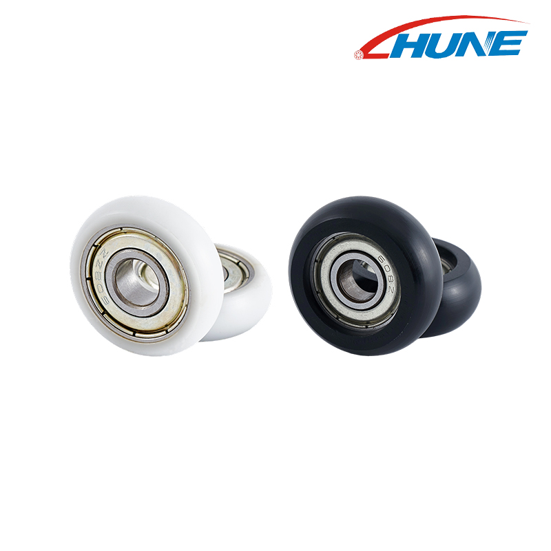
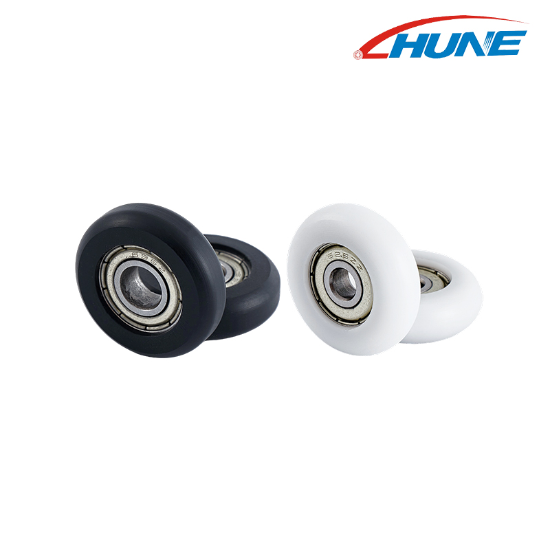
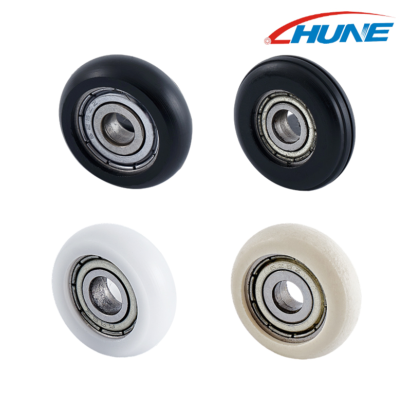
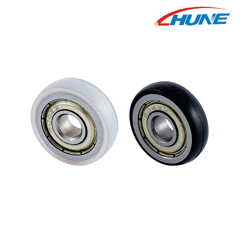
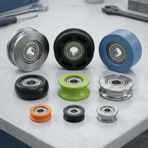
Guide wheels and track rollers can look almost identical when they are sitting on a workbench. Both are round. Both can contain bearings. Both may run against a rail, profile, or other moving surface.
That is where the confusion starts.
In an actual machine, these two components may have quite different jobs. A guide wheel is often used to keep a moving part on course, while a track roller may be designed to run along a defined track while carrying or transferring part of the working load. In some equipment, one component can even perform both functions.
So, what is the practical difference between a guide wheel and a track roller?
The answer comes down less to the name printed on a product page and more to how the wheel interacts with the machine around it.
Guide Wheel vs. Track Roller at a Glance
Before looking at the details, it helps to separate the basic roles.
| Consideration | Guide Wheel | Track Roller |
|---|---|---|
| Main role | Helps control movement or alignment | Runs along a defined track or rail |
| Contact | May contact a rail, panel, edge, or profile | Usually designed around a specific track surface |
| Load function | Can guide, stabilize, or carry part of a load | Often combines rolling movement with load transfer |
| Typical structure | Wheel, bearing, shaft, or mounting arrangement | Roller body, bearing, stud, shaft, or mounting structure |
| Profile | Flat, grooved, flanged, or custom | Often matched to a track or cam profile |
| Design focus | Movement control and alignment | Track contact, rolling movement, and load transfer |
These are general distinctions rather than strict industry definitions. Machine builders often use the terms differently, and a component described as a guide wheel in one application may be called a track roller in another.
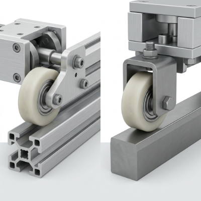
The important question is: What is the wheel actually doing inside the mechanism?
What Does a Guide Wheel Do?
A guide wheel is mainly concerned with direction.
Imagine a movable panel travelling along a frame. Without some form of guidance, the panel may move sideways, rub against the surrounding structure, or gradually drift away from its intended path.
A guide wheel helps control that movement.
It may run along a rail, inside a channel, against a side surface, or along another part of the machine. Depending on the design, it can also support some of the moving section.
Guidance Does Not Always Mean Load Bearing
This is an easy distinction to miss.
Some guide wheels mainly keep a moving assembly aligned. They are not necessarily carrying the full weight of that assembly.
For example, a moving carriage might have separate wheels that support its weight and smaller wheels that keep it centered on the track. Both are rolling components, but their mechanical responsibilities are different.
That difference affects how the wheel should be designed.
A wheel used mainly for lateral guidance may have different requirements from one expected to support a substantial portion of the moving structure.
Then What Is a Track Roller?
A track roller is generally designed around a defined running path.
The track might be a rail, cam, guide profile, or specially shaped surface. The roller follows that path as the machine moves.
In many designs, the roller also transfers load between the moving assembly and the track. That means the contact surface, bearing arrangement, mounting structure, and roller profile all become closely connected.
A track roller is therefore not simply a wheel that happens to touch a rail.
The track is part of the design.
If the track has a particular shape, the roller needs to work with that shape. If the roller is mounted through a stud or shaft, the surrounding structure needs to accommodate that connection as well.
The Real Difference Often Appears at the Contact Surface
If you have two wheels that look similar, look at what they touch.
That usually tells you more than the product name.
A guide wheel may run against the side of a profile to stop a carriage from moving sideways. Another may sit in a groove and help keep a moving section centered.
A track roller, on the other hand, is often designed to follow a defined track surface. Its outer profile may be shaped specifically for that interface.
Common Contact Arrangements
Several arrangements can appear in industrial equipment:
- Flat wheel against a flat running surface
- Grooved wheel around a rail or suitable profile
- Flanged wheel beside a track
- Convex or concave wheel against a matching surface
- Roller following a cam or formed track
- Custom wheel profile for a specialized mechanism
The shape of the wheel should not be selected independently from the mating surface.
A groove that looks suitable in a catalog may not work with an actual rail if the contact relationship is different.
A Simple Example: One Carriage, Several Jobs
Consider a small industrial carriage moving along a frame.
The carriage needs to travel forward and backward. It also needs to stay centered and avoid lifting or shifting sideways.
The machine may use several rolling components.
One group carries the carriage through its main travel direction. Another group provides side guidance. A third contact point may prevent excessive movement away from the track.
All of these components roll, but they do not necessarily perform the same job.
This is why replacing every wheel with the same type can create problems.
The mechanical role matters more than the fact that all of them are round.
Where Bearings Fit Into the Difference
Bearings are another reason guide wheels and track rollers can look similar while behaving differently.
A bearing allows the wheel or roller to rotate around its shaft or mounting point. But the bearing does not determine the entire function of the component.
The outer wheel still needs to make suitable contact with the track or guide surface.
A useful way to think about the assembly is:
- Bearing: Supports rotation
- Wheel profile: Manages contact
- Shaft or mounting: Connects the component to the machine
- Track or guide surface: Defines the running path
If one part of that relationship is wrong, changing another part may not solve the problem.
For example, a bearing can rotate freely while the wheel still rubs against an unsuitable track.
Load Direction Can Change the Design
A wheel may look simple from the outside, but forces inside the machine can arrive from several directions.
Depending on the equipment, the roller may experience:
- Radial loading
- Side loading
- Axial force
- Changing force during movement
- Vibration
- Intermittent impact
- Combined loading
A guide wheel that mainly controls sideways movement may have a different mechanical requirement from a track roller carrying a moving carriage.
This is one reason industrial roller selection should start with the application rather than the outside diameter or wheel appearance.
Why Track Shape Matters So Much
The track and roller form a working pair.
Suppose a track has a curved running surface. A flat wheel will create a different contact condition from a wheel designed to match that curve.
Likewise, a grooved wheel needs a compatible track. If the groove is too loose, the wheel may have unwanted side movement. If the contact is too restrictive, movement may become difficult.
The same principle applies to custom industrial equipment.
Think About the Whole Running Path
Do not inspect only the straight section.
Check what happens when the roller:
- Starts moving.
- Reaches normal travel.
- Changes direction.
- Passes a joint or transition.
- Enters a curved section.
- Stops under load.
A wheel that behaves well in one section may react differently when the geometry changes.
For equipment manufacturers, this is particularly useful during prototype testing.
Guide Wheel or Track Roller: Which One Does Your Machine Need?
1. Is the Component Mainly Controlling Alignment?
If the main purpose is to prevent a panel, carriage, belt, cable, or other moving section from drifting, a guide wheel may describe the role more accurately.
2. Does the Wheel Run Directly Along a Defined Track?
If the roller follows a rail, cam, or formed running path as part of the machine's movement, a track roller may be the more useful description.
3. Does It Carry Part of the Load?
If the wheel transfers a meaningful portion of the moving assembly's load into the track, that needs to be included in the design discussion.
4. Is the Profile Matched to the Track?
A specialized groove, flange, or curved profile suggests that the wheel and running surface should be considered as one interface.
5. Is the Component Part of a Custom Mechanism?
If the existing machine has a special shaft, bracket, limited installation area, or unusual track profile, a standard catalog description may not tell the whole story.
What Should Be Included in a Roller Inquiry?
When sourcing a guide wheel or track roller for industrial equipment, a short description of the application is much more useful than a product name alone.
A supplier or engineering team will usually need to understand several parts of the mechanism.
| Information | Why It Helps |
|---|---|
| Machine application | Shows the component's actual role |
| Running surface | Defines the wheel-to-track relationship |
| Wheel profile | Helps establish contact geometry |
| Mounting method | Shows how the component connects to the machine |
| Load direction | Helps understand force transfer |
| Movement pattern | Indicates how the roller operates |
| Material environment | Supports material selection |
| Available space | Helps avoid interference during installation |
| Existing sample | Useful when developing a replacement |
| Drawing or photo | Makes the assembly easier to understand |
An existing sample can be particularly helpful when the machine is already in production.
Even if the original component is worn, its mounting arrangement and contact profile can provide useful clues.
Can One Roller Work as Both a Guide Wheel and a Track Roller?
Yes, depending on the machine design.
The terms are not mutually exclusive.
A roller can guide a moving assembly while also carrying part of its load. In another design, a wheel may follow a track and mainly provide positioning.
This overlap is one reason terminology can become confusing when purchasing components.
For custom equipment, it is often better to describe the function directly.
For example:
"Roller follows a rail and supports the carriage."
Or:
"Wheel keeps the panel aligned against the side guide."
That type of description gives an engineering team much more useful information than simply saying, "I need a guide wheel."
When Customization Becomes Part of the Solution
Not every machine can use a standard wheel.
The problem may not be the wheel itself. It may be the combination of wheel, bearing, shaft, bracket, track, and available space.
A custom roller may be considered when the equipment has:
- A non-standard running profile
- A special groove or flange
- Limited mounting space
- A particular shaft arrangement
- A specific bearing position
- A special material requirement
- A combination of guiding and load-support functions
Customization does not necessarily mean redesigning the entire mechanism.
Sometimes the change is limited to the wheel profile. In another project, the bearing arrangement or mounting connection may need to change.
The starting point should always be the machine.
A Better Way to Compare the Two
If you are comparing guide wheels and track rollers for a new project, try describing them in terms of function rather than category.
| Question | What to Find Out |
|---|---|
| What moves? | Panel, carriage, belt, cable, material, or another assembly |
| What stays fixed? | Rail, frame, profile, guide, or track |
| Where does contact occur? | Top, bottom, side, groove, or multiple surfaces |
| What does the wheel control? | Direction, alignment, load, or a combination |
| How is it mounted? | Shaft, stud, bracket, housing, or integrated structure |
| What happens during movement? | Straight travel, reversing, curves, vibration, or changing load |
Once these answers are clear, the difference between a guide wheel and a track roller becomes much easier to understand.
Frequently Asked Questions
Are Guide Wheels and Track Rollers the Same Thing?
Not always. Both are rolling components, but their functions can differ. A guide wheel may mainly control alignment, while a track roller often follows a defined track and may also transfer part of the working load.
Can a Guide Wheel Carry a Load?
Yes. A guide wheel can carry some load depending on the machine design. However, its actual load function should be confirmed from the complete mechanism rather than assumed from the name.
Does the Track Shape Affect Roller Selection?
Yes. The track determines how the wheel contacts the machine. Flat, grooved, curved, flanged, and enclosed running surfaces can require different wheel profiles and mounting arrangements.
Why Does the Bearing Matter?
The bearing supports the rotation of the wheel around its mounting point. Its fit, position, and relationship with the shaft and wheel can affect how the complete assembly operates.
Can a Custom Guide Wheel Also Be Used as a Track Roller?
It can, depending on its design and working conditions. If the component needs to guide movement while also carrying or transferring load through a track, those functions should be considered together during development.
The difference between a guide wheel and a track roller is not always obvious from the outside. Both can use similar wheel bodies, bearings, shafts, and materials.
The clearer distinction comes from the job each component performs.
A guide wheel is generally concerned with keeping movement controlled and aligned. A track roller is usually designed around a defined running path and may also support or transfer load through that track.
But real machines are not always that tidy. One roller can perform several functions at once.
For equipment designers and purchasing teams, the practical approach is to describe the complete working situation. Look at the track, contact surface, movement direction, load, mounting structure, bearing arrangement, available space, and operating environment.
Once those details are understood, the product name becomes less important. The roller can then be designed around what the machine actually needs to do.