

 English
 Español
 日本語
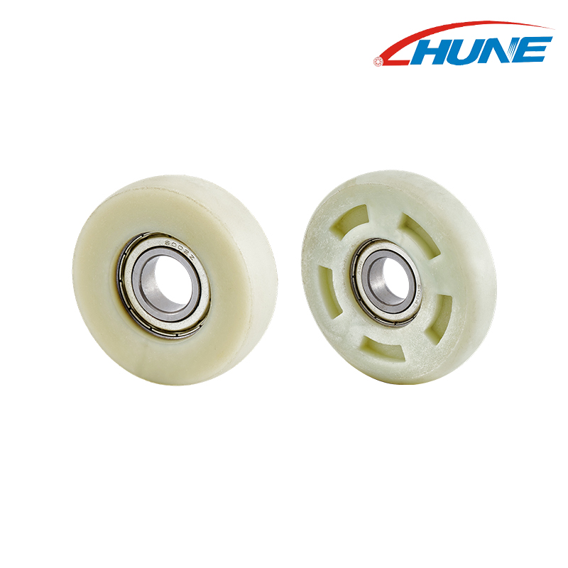
日本語Guide rollers are used in many types of industrial equipment where a moving part needs to stay on a controlled path. Sometimes the roller supports the movement directly. In other machines, it simply keeps a belt, panel, carriage, cable, or material from drifting away from its intended position.
The component itself can be quite small, especially in compact machinery. That does not mean its function is limited. A small roller may sit inside a packaging machine, guide a moving section of an automated system, support a conveyor mechanism, or help control the position of a material as it passes through several stages of production.
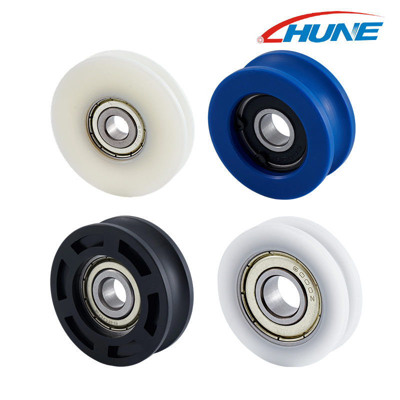
This makes guide rollers an interesting component category for equipment manufacturers. The same basic idea can be adapted to very different mechanical structures, with changes to the wheel profile, material, bearing arrangement, shaft connection, or mounting method.
Where Do Guide Rollers Appear In Industrial Machinery?
There is no single machine type associated with guide rollers.
They can be found wherever controlled movement is needed, particularly when a component has to travel repeatedly through a fixed route. The roller may run against a rail, profile, belt, panel, cable, or another moving surface.
Common application areas include:
- Conveyor and material handling equipment
- Packaging machinery
- Automated production equipment
- Printing machinery
- Textile equipment
- Industrial doors and movable panels
- Logistics and sorting systems
- Machine access structures
- Compact transmission mechanisms
- Various customized industrial assemblies
The actual construction can be very different from one application to another. A roller used beside a conveyor belt may have little in common visually with a small roller installed inside packaging equipment, even though both perform a guiding function.
Conveyor Systems Are A Natural Place For Guide Rollers
Conveyor equipment has to move products continuously while keeping them within a defined route. Depending on the machine design, guide rollers can help control lateral movement or support a particular section of the conveying process.
A belt, for example, does not simply move forward. It also responds to the load placed on it, the condition of the frame, the drive arrangement, and the alignment of the conveyor. A guide element can help keep the moving belt within the intended area.
Belt Guidance Depends On The Whole Structure
It would be too simple to say that a guide roller alone determines whether a conveyor tracks correctly.
The conveyor frame, belt, drive components, rollers, tension, installation, and guide arrangement all interact. If one part is misaligned, the belt may behave differently even when the guide roller itself is correctly manufactured.
For equipment manufacturers, this means the roller should be selected according to the complete conveyor structure rather than treated as an isolated replacement part.
Packaging Machines Have Another Kind Of Guiding Requirement
Packaging equipment often works with materials that are continuously fed through the machine.
Film, paper, labels, flexible packaging materials, cartons, and other components may need to change direction or pass through different processing stations. Rollers can help keep these materials moving along the intended route.
The roller may also need to fit inside a relatively compact space, which changes the design considerations compared with larger conveying equipment.
Flexible Materials Need Controlled Contact
A rigid box and a thin film do not behave in the same way when they meet a roller.
With flexible materials, the contact surface can influence how the material travels through the machine. The position of the roller matters as well because even a small change in the path can affect how the material reaches the next stage.
For this type of application, manufacturers may consider the wheel surface, material, bearing support, mounting structure, and surrounding clearance together.
Automation Equipment Brings More Moving Parts
Modern production equipment can contain several moving sections within one machine.
A carriage may travel along a guide. A panel may move into position. A transfer mechanism may shift a product between stations. A machine cover may slide open during maintenance and return to its original position afterward.
Guide rollers can be incorporated into these mechanisms when the moving section needs additional support or controlled contact.
Small Rollers Can Fit Into Tight Mechanisms
One reason rollers are useful in automation equipment is their relatively compact construction.
A machine designer may have limited room around a rail, bracket, shaft, or moving frame. A roller with an appropriate bearing arrangement can be integrated into that structure without requiring a large supporting mechanism.
This is where customized roller construction can become relevant. The required wheel profile or mounting structure may be determined by the machine rather than by a standard catalog design.
Printing Equipment Uses Small Rolling Components Too
Printing machinery provides another example where guided movement is important.
Paper, labels, film, and other media need to pass through different sections of a machine in a controlled sequence. Small rollers can help guide the material as it changes direction or moves between components.
The roller does not necessarily carry a large mechanical load. Instead, its job may be to maintain the position of the moving material and keep the intended path consistent.
Space Can Be A Major Design Consideration
Inside compact printing equipment, components can be positioned very close together.
A roller may need to fit around an existing shaft, bracket, housing, or neighboring component. The outer wheel shape is therefore only part of the design.
The internal bearing arrangement and mounting method can be equally important because they determine how the roller connects to the machine.
Textile Equipment Requires Continuous Guidance
Textile machinery is another environment where rollers can play a useful role.
Yarn, thread, fabric, and other flexible materials may move continuously through production equipment. Their direction can change several times before the material reaches the next processing stage.
A guide roller can help establish that route while allowing the material to move through the machine with controlled contact.
The Surface Needs To Match The Material
The contact between a roller and textile material needs to be considered carefully.
Different materials respond differently to friction, pressure, surface texture, and movement speed. The roller therefore needs to be considered as part of the material-handling path rather than as a generic wheel.
Depending on the application, manufacturers may evaluate plastic, metal, rubber-coated, or other roller constructions.
Industrial Doors And Moving Panels Use A Similar Principle
Guide rollers are not limited to production machinery.
Industrial doors, movable panels, machine covers, partitions, and similar structures may also need rollers to keep movement aligned with a track or frame.
The wheel may run inside a guide channel, along a profile, or against a supporting surface. Its shape needs to correspond to that contact relationship.
Wheel Profile Can Change The Way The Roller Runs
A flat wheel, grooved wheel, flanged wheel, and other profiles create different contact conditions.
For example, a groove may help keep a cable or suitable track within a defined position, while a flange can provide lateral guidance along a compatible surface.
The important point is not that one shape is suitable for every machine. The profile needs to match the geometry of the mating component.
Logistics Equipment Also Relies On Controlled Movement
Warehouses and production facilities contain many systems designed to move products from one location to another.
Conveyors, sorting equipment, transfer mechanisms, movable platforms, and other handling structures can use rollers as part of their guidance systems.
A roller may support a product directly, guide a belt, or control the movement of another mechanical section.
In these applications, repeated movement is part of normal operation, so the wheel, bearing, axle, and mounting structure need to work together rather than being selected separately.
What Materials Can Be Used For Guide Rollers?
Material selection depends on the machine and its operating environment.
Metal is often considered when the assembly calls for a rigid wheel structure. Engineering plastics may be useful when weight, contact behavior, corrosion considerations, or noise need to be considered. Rubber or elastomeric surfaces can provide a different interaction with the mating component.
There is no need to select a material simply because it is commonly used in another machine.
| Material Type | Application Considerations |
|---|---|
| Steel | Rigid mechanical structures and industrial environments |
| Stainless steel | Applications where moisture or corrosion exposure matters |
| Engineering plastics | Compact mechanisms and specific contact requirements |
| Rubber or elastomer | Surface contact, grip, and cushioning considerations |
| Brass | Specialized mechanical and environmental conditions |
The surrounding track or contact surface matters just as much as the wheel material.
The Bearing Is Part Of The Roller Design
A guide roller with a bearing has more going on internally than the outside wheel suggests.
The bearing supports rotation around the shaft or mounting point. Its position, fit, and relationship with the wheel can influence the overall movement of the assembly.
For industrial applications, manufacturers may need to consider:
- Shaft arrangement
- Bearing position
- Available mounting space
- Expected movement
- Environmental conditions
- Load direction
- Installation method
A suitable outer wheel profile cannot compensate for an unsuitable internal structure.
Why The Bearing And Wheel Should Be Considered Together
Imagine a roller that fits the track correctly but does not fit the existing shaft arrangement.
The wheel shape may be appropriate, but the component still cannot be integrated into the machine without changing the surrounding structure.
This is why a roller drawing or sample can be useful during product development. It allows the wheel, bearing, shaft, and mounting structure to be considered as one assembly.
Not Every Guide Roller Carries The Same Load
Another point that is easy to overlook is the difference between guiding and supporting.
Some rollers carry part of the weight of a moving assembly. Others mainly control lateral position. Some have relatively light contact and operate as part of a guiding mechanism.
That difference affects how the component should be selected.
A roller intended to guide a belt edge may have a very different mechanical requirement from one supporting a moving machine carriage.
Direction Of The Force Matters
The load on a roller is not always directly downward.
Depending on the mechanism, forces may act:
- Radially
- Laterally
- Along the shaft
- At an angle
- Through changing directions during movement
Understanding how the force reaches the roller helps determine the appropriate wheel and bearing arrangement.
This is especially important for custom industrial components because the roller may be designed around a specific machine rather than used as a general-purpose part.
What Should Manufacturers Check Before Ordering?
For a new industrial project, the easiest way to start a roller discussion is to describe the application.
A simple photograph can help, but a drawing or existing sample can provide additional information about the mounting structure.
Useful information includes:
| Information | Purpose |
|---|---|
| Application | Shows what the roller actually does |
| Wheel position | Helps understand the movement |
| Running surface | Defines the contact relationship |
| Shaft or axle | Helps determine the internal arrangement |
| Material environment | Helps with material selection |
| Load direction | Helps evaluate the mechanical structure |
| Available space | Important for compact machinery |
| Existing sample | Useful for replacement development |
| Drawing | Useful for customized production |
This approach is more practical than choosing a roller based only on its outside appearance.
When Does A Customized Guide Roller Make Sense?
Standard components can work well when the machine already follows a common design. Specialized equipment can be different.
A manufacturer may have an existing shaft, housing, rail, groove, bracket, or frame that cannot easily be changed. In that situation, the roller needs to adapt to the machine.
Customization may involve the wheel profile, material, bearing arrangement, shaft connection, flange, groove, or other structural details.
The process can begin with a drawing, sample, photograph, or simple description of the mechanism.
Development Usually Starts With The Application
Rather than asking only, "What roller do you have?", a more useful starting point is:
Where will the roller be installed?
What will it contact?
How will it move?
What supports the roller?
What space is available around it?
Once these questions are clear, the mechanical design becomes easier to discuss.
Guide Rollers Are Not Limited To One Industry
The wide range of applications comes from a simple mechanical requirement: controlled movement.
A conveyor needs products or belts to follow a route. A packaging machine needs film or cartons to move between stations. A textile machine needs yarn or fabric to follow a defined path. An automated system needs a carriage or panel to stay aligned. A printing machine needs media to move through a compact internal structure.
The equipment is different, but the basic function can be similar.
That is why guide rollers can appear in machines that look completely unrelated to each other.
The Small Component Behind A Larger Movement
Guide rollers may not be the largest parts inside industrial equipment, but they can have a direct relationship with how a moving assembly behaves.
Wheel geometry affects contact. Material affects the interaction with the surrounding surface. Bearings support rotation. The axle determines how the roller connects to the machine. The bracket establishes its position. The surrounding frame determines how forces are transferred.
Looking at these parts separately can make component selection unnecessarily complicated.
A more practical approach is to start with the movement and work backward toward the roller design.
For equipment manufacturers, this means considering the running surface, movement direction, load, environment, available space, wheel profile, bearing arrangement, and mounting structure before finalizing the component.
That approach also leaves room for customization when a standard roller does not fit the machine.
Guide rollers are used across conveyor systems, automation equipment, packaging machinery, printing equipment, textile machinery, logistics systems, industrial doors, and many other mechanical applications. Their specific form may change from one machine to another, but their purpose remains closely connected to controlled movement.
For buyers and equipment designers, the key is not simply finding a wheel that looks suitable. The useful question is whether the complete roller assembly fits the way the machine moves, what it contacts, and how it is mounted.
That is where the right combination of wheel geometry, material, bearing support, and mounting structure becomes part of the overall equipment design.